Preventing Failure When Replacing a 300A Phase Control SCR
A failed thyristor can stop an entire production line, but replacing the semiconductor without identifying the cause of failure may lead to another breakdown. High-current rectifier systems are interconnected assemblies in which the gate circuit, transformer, busbars, protection devices, cooling system, and load all affect semiconductor stress. A proper replacement process therefore begins with diagnosis and ends with controlled commissioning.
This is particularly important in melting furnace rectifiers gate trigger control 300A phase control thyristor installations, where rapidly changing loads and high electromagnetic interference can place severe demands on both the power device and its trigger circuit. The new thyristor must be correctly selected, correctly mounted, and supported by a healthy surrounding system.
1. Identify the Original Failure Mode
Before removing the failed device, technicians should document the condition of the rectifier. Check for blown fuses, overheated cables, discolored busbars, damaged gate wiring, loose connections, blocked ventilation, unusual odors, and signs of arcing.
A thyristor may fail short-circuit because of excessive current, overvoltage, overheating, or an uncontrolled rate of current rise. It may fail open-circuit because of internal bond damage, severe thermal cycling, or mechanical stress. In some cases, the thyristor is not actually defective; the gate driver may have stopped producing a pulse, or the current path may be interrupted elsewhere.
Failure analysis should include measurements of the snubber resistor and capacitor, gate resistance, pulse transformer continuity, heat-sink temperature sensor, cooling fan operation, and semiconductor fuse condition. Replacing only the visible failed part can leave the actual root cause unresolved.
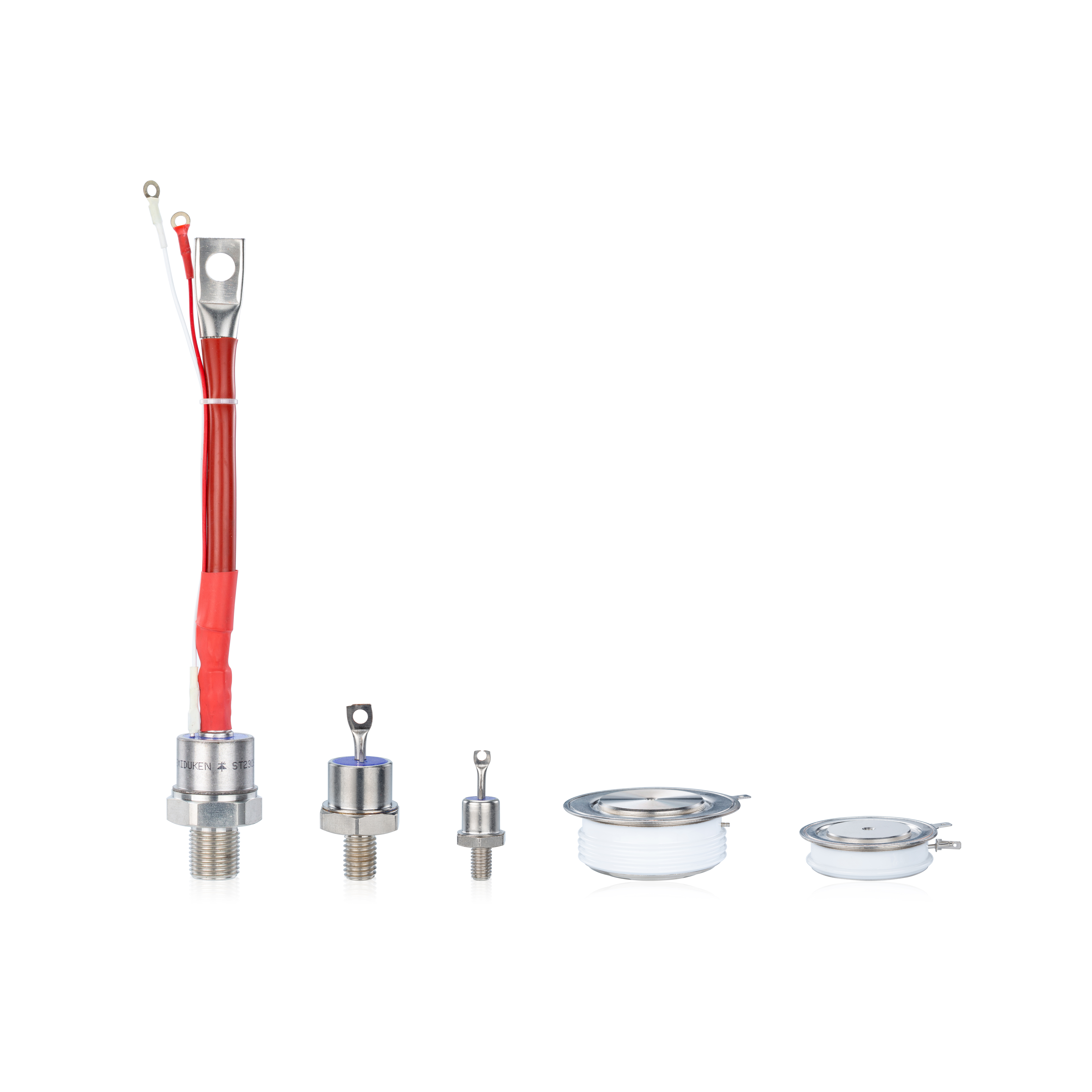
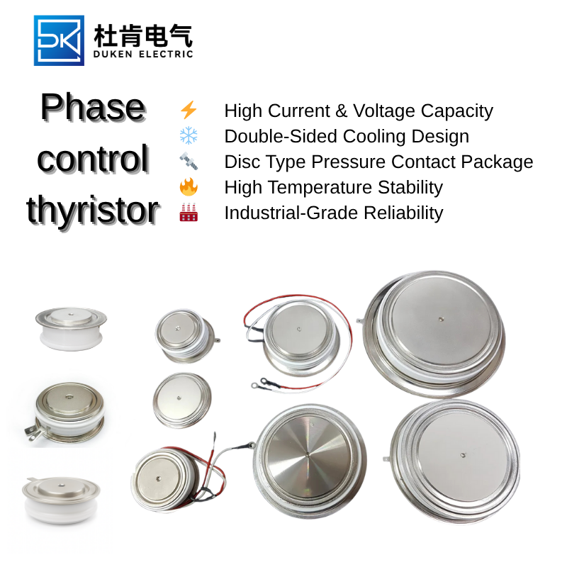
An Aluminium housing disc package for electro-plating rectifiers 300A phase control thyristor should also be inspected for uneven contact patterns. Darkened or oxidized areas on one pole face may indicate insufficient clamping pressure or poor surface flatness. These conditions increase thermal resistance and create localized heating.
2. Select the Correct Electrical Replacement
The new device should equal or exceed the original repetitive blocking voltage, average current, RMS current, surge current, I²t capability, and maximum junction temperature. However, unnecessarily oversizing every rating is not always ideal. A device with a much larger die may have different gate characteristics and may not respond correctly to the existing firing circuit.
For applications emphasizing low on-state voltage drop for DC link rectification in drives 300A phase control thyristor performance, engineers should compare on-state voltage at the actual operating current rather than only at the manufacturer’s headline test point. Two devices can have the same nominal current rating but different conduction losses under real load conditions.
The rate of rise of on-state current, or di/dt, must also be considered. During initial turn-on, conduction begins in a limited region near the gate and spreads across the die. If anode current rises too quickly, local heating can damage the device before the entire junction is conducting. Series inductance and a strong gate pulse help manage this condition.
Voltage transient capability is equally important. Transformer commutation, contactor operation, and load switching can produce spikes that exceed the normal line voltage. The replacement should have adequate voltage margin, but the snubber and surge suppression network must also function correctly.
3. Confirm Gate Drive Compatibility
A thyristor can have excellent power ratings and still perform poorly if the gate driver is not compatible. The gate trigger current, trigger voltage, pulse width, and latching behavior should be compared with the original component.
In melting furnace rectifiers gate trigger control 300A phase control thyristor equipment, firing pulses may be synchronized with a three-phase supply and adjusted continuously to regulate furnace power. A weak or distorted pulse can cause delayed turn-on, phase imbalance, and excessive transformer heating.
Gate pulses should be measured with properly isolated equipment. The waveform should be checked at both low and high firing angles, because some control boards produce different pulse widths across the adjustment range. The gate-cathode loop should be short and protected from interference. Loose gate terminals can create intermittent conduction that may be mistaken for a power-stage problem.
The latching current of the replacement must suit the load. If the anode current builds slowly, the gate pulse may need to remain active longer. Repetitive gate pulses can improve reliability in difficult inductive loads, but only if permitted by the gate power limits.
4. Install the Device Correctly
Mechanical installation is critical for disc thyristors. The pole faces and heat-sink surfaces must be clean, smooth, and aligned. The specified clamping force should be applied with the correct hardware and verified when possible.
An Aluminium housing disc package for electro-plating rectifiers 300A phase control thyristor may be exposed to moisture, chemical vapor, and conductive contamination. The enclosure should be cleaned, air filters replaced, and terminals protected against corrosion. Contamination can create leakage paths and increase the risk of flashover.
Cooling must be restored before testing. Fans should rotate in the correct direction, water passages should be clear, and thermal sensors should make proper contact. The expected power loss should be calculated using realistic current and conduction angle values.
Selecting a low on-state voltage drop for DC link rectification in drives 300A phase control thyristor can reduce thermal stress, but it does not eliminate the need for correct cooling. Even an efficient device may dissipate substantial power during continuous high-current operation.
5. Commission the Rectifier in Stages
After installation, the system should be energized gradually. Begin with visual inspection and resistance checks before applying control power. Confirm that the gate board receives the correct supply voltage and that firing pulses are present.
Where possible, test the rectifier at reduced input voltage or with a limited load. Compare the current in each phase, observe the DC output waveform, and monitor the temperature of each heat sink. Unequal heating can indicate an incorrect firing angle, weak gate pulse, damaged transformer winding, or poor mechanical contact.
A replacement used in melting furnace rectifiers gate trigger control 300A phase control thyristor service should be monitored through a complete heating cycle. A replacement used as an Aluminium housing disc package for electro-plating rectifiers 300A phase control thyristor should undergo a sustained load test because thermal problems may develop slowly.
During drive testing, verify that the low on-state voltage drop for DC link rectification in drives 300A phase control thyristor provides the expected efficiency without abnormal current sharing or commutation behavior. Record temperatures and electrical measurements so that future maintenance teams have a baseline.
Preventing repeat failure requires more than installing a new semiconductor. It requires identifying the original cause, matching all critical ratings, confirming gate compatibility, applying correct mounting pressure, restoring cooling, and validating the complete rectifier under controlled conditions. This disciplined approach reduces downtime and protects both the new thyristor and the equipment around it.