A Practical Engineering Guide to 300A Thyristor Replacement
A 300A phase control thyristor is a critical component in many industrial power systems. It may regulate transformer output, control a heating process, provide adjustable DC voltage, or manage the input stage of a motor drive. When the original part becomes obsolete or fails unexpectedly, engineers must find a replacement that can operate safely within the existing electrical and mechanical design.
The selection process should begin with the original data sheet, but it should not end there. Real equipment may operate under conditions that differ from ideal catalog tests. Ambient temperature may be higher, cooling performance may have deteriorated, or the load may produce larger current peaks than expected.
In melting furnace rectifiers gate trigger control 300A phase control thyristor service, for example, the device must withstand demanding thermal cycles and maintain reliable firing as the furnace impedance changes. A practical replacement strategy must evaluate the entire installation.
1. Create a Complete Replacement Specification
Start by recording the original thyristor part number, package dimensions, voltage class, current ratings, surge current, I²t value, gate trigger current, gate trigger voltage, holding current, latching current, thermal resistance, and maximum junction temperature.
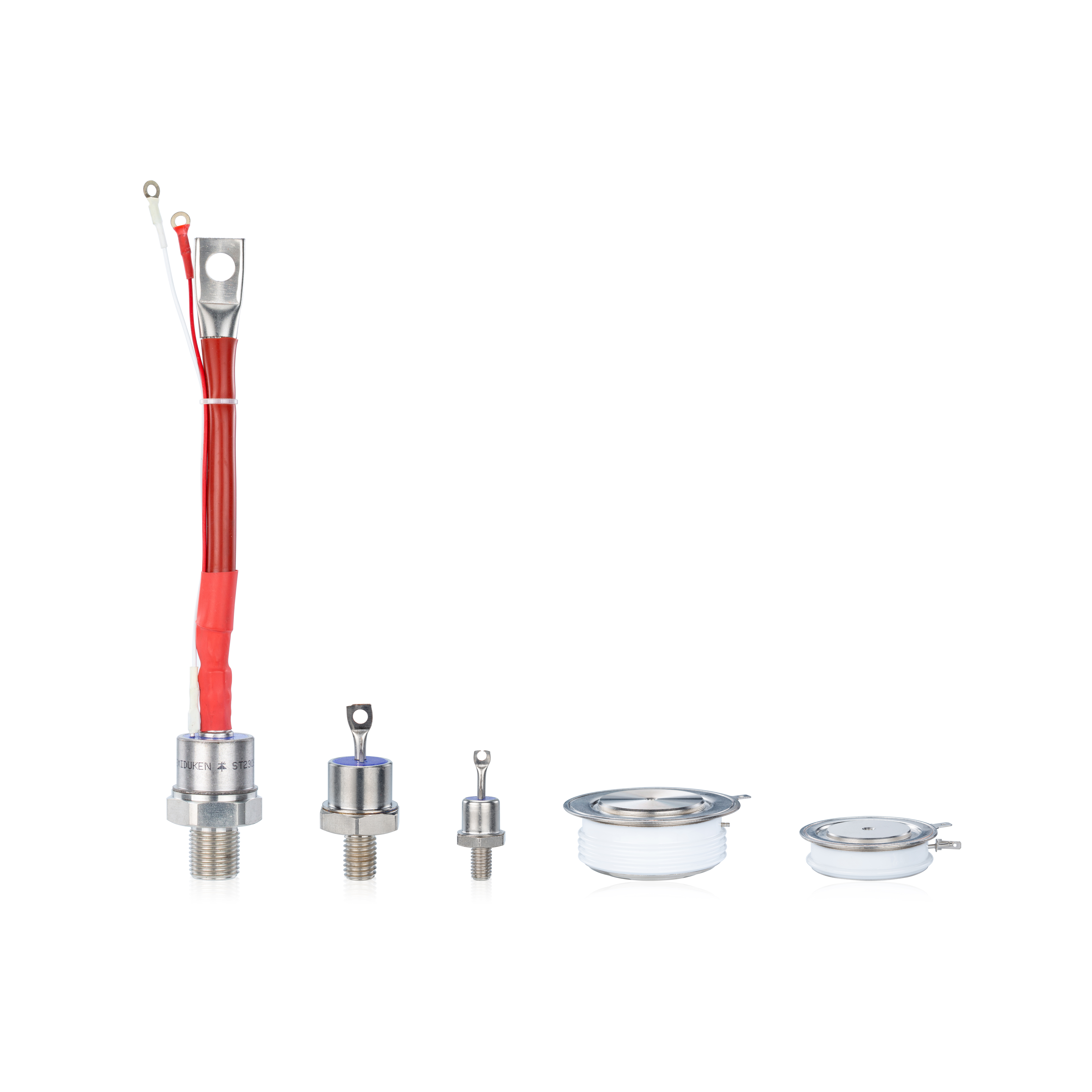
Mechanical information is equally important. Measure the disc diameter, pole-face diameter, total height, gate terminal position, polarity markings, and required mounting force. A physically incompatible device can create alignment problems or prevent the original clamp from applying uniform pressure.
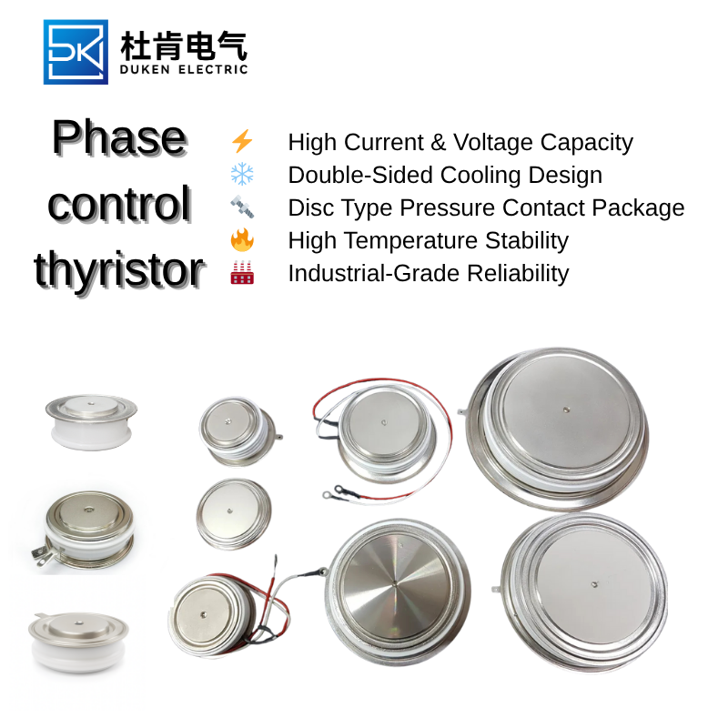
An Aluminium housing disc package for electro-plating rectifiers 300A phase control thyristor may appear similar to another disc device, but small dimensional differences can affect thermal contact or busbar clearance. Engineers should compare mechanical drawings rather than relying on photographs.
The replacement specification should also include the actual operating current, line voltage, firing-angle range, cooling method, ambient temperature, and load type. This information allows a supplier or design engineer to recommend a part based on the real duty rather than a nominal rating.
2. Compare Losses and Thermal Margin
The on-state voltage of the thyristor determines a large part of its conduction loss. At high current, this loss becomes a major source of heat. The thermal system must maintain the junction below its maximum temperature under the worst expected load.
Choosing a low on-state voltage drop for DC link rectification in drives 300A phase control thyristor can provide additional thermal margin. Lower heat generation may reduce fan demand, slow insulation aging, and improve the reliability of neighboring capacitors, control boards, and wiring.
Thermal calculations should include the maximum on-state voltage rather than only a typical value. The engineer should estimate average power loss using the expected current waveform and conduction angle. This value can then be combined with junction-to-case, case-to-sink, and sink-to-ambient thermal resistance.
Cooling performance should be measured when possible. A heat sink that was adequate when new may have become less effective because of dust, corrosion, blocked airflow, or reduced water flow. Replacing the thyristor without restoring the cooling system can result in another failure.
3. Review the Gate and Protection Circuits
Gate trigger compatibility is essential. A replacement with a higher trigger requirement may not receive sufficient current from the original firing board. The result can be unstable turn-on, excessive delay, or failure to conduct at certain firing angles.
For melting furnace rectifiers gate trigger control 300A phase control thyristor installations, the gate pulses should be checked during startup, low power, and full power operation. Furnace control systems may change the firing angle continuously, and a marginal gate circuit may fail only in part of this range.
The snubber network should also be inspected. A damaged capacitor or open resistor can expose the thyristor to excessive dv/dt and transient voltage. Semiconductor fuses must have suitable voltage, current, and I²t characteristics. Ordinary industrial fuses may not clear rapidly enough to protect the device during a short circuit.
Gate cables should be separated from power conductors where possible. Shielding, twisted gate-cathode pairs, and secure terminal connections reduce the chance of noise-induced triggering.
4. Install and Test the New Device
Before installation, clean the heat-sink surfaces and check them for damage. The thyristor should be centered in the clamp, and the specified mounting pressure should be applied evenly. The gate lead must not carry mechanical force or become trapped between conductive parts.
An Aluminium housing disc package for electro-plating rectifiers 300A phase control thyristor installed in a chemically aggressive environment should receive additional attention. The enclosure must limit exposure to moisture and corrosive vapor, while cooling passages and filters should be kept clean.
Initial power-up should be controlled. Confirm the polarity and gate connections before energizing the main circuit. If possible, begin with reduced voltage or a limited load. Check the firing pulses, phase current, DC output, and temperature rise.
A low on-state voltage drop for DC link rectification in drives 300A phase control thyristor should demonstrate stable conduction across the drive’s operating range. Current should be balanced, and the device should not show abnormal heating compared with the other phases.
5. Establish a Long-Term Reliability Plan
After the replacement is commissioned, record the installation date, part number, electrical measurements, heat-sink temperatures, cooling conditions, and clamping details. These records provide a useful baseline for future maintenance.
A rectifier using melting furnace rectifiers gate trigger control 300A phase control thyristor components should be inspected regularly for gate pulse quality, phase balance, transformer noise, and cooling performance. Changes in these conditions can provide early warning of a developing fault.
For an Aluminium housing disc package for electro-plating rectifiers 300A phase control thyristor, maintenance should include checking for corrosion, chemical contamination, loose joints, and restricted airflow or water flow. Continuous-duty equipment can accumulate thermal and environmental damage gradually.
Drive systems using a low on-state voltage drop for DC link rectification in drives 300A phase control thyristor should be monitored for rising cabinet temperature, capacitor aging, and changes in line current. These indicators can reveal cooling degradation or abnormal loading before a semiconductor fails.
A reliable replacement is the result of disciplined engineering rather than part-number substitution. The device must fit the original assembly, respond to the existing gate circuit, tolerate voltage and current stress, transfer heat effectively, and operate under the real application duty. By combining careful specification, controlled installation, protective-circuit inspection, and long-term monitoring, engineers can extend rectifier life and reduce unplanned production downtime.