Improving Rectifier Efficiency with the Right 300A Thyristor
Efficiency in a high-current rectifier is influenced by transformer losses, semiconductor conduction loss, busbar resistance, cooling power, control strategy, and load characteristics. Although a thyristor is only one component in the system, selecting the correct device can produce measurable improvements in temperature, stability, and operating cost.
The benefits are especially important in continuously operating industrial equipment. A plating line may run for an entire shift, while a drive system may spend thousands of hours per year converting AC power into a controlled DC link. Furnace rectifiers may experience repeated high-current heating cycles. In each case, the thyristor must handle the required current while maintaining low loss and predictable triggering.
A system designed around melting furnace rectifiers gate trigger control 300A phase control thyristor operation must balance power control accuracy with high-current reliability. Efficient operation requires both a capable semiconductor and a properly coordinated firing system.
1. Understand Where Thyristor Losses Come From
During conduction, a thyristor develops an on-state voltage across its anode and cathode. Multiplying this voltage by current gives instantaneous conduction loss. Because the device may conduct for only part of each AC cycle, the actual average loss depends on current waveform, firing angle, supply frequency, and load behavior.
At 300A, a relatively small voltage drop represents substantial heat. For this reason, low on-state voltage drop for DC link rectification in drives 300A phase control thyristor selection is valuable in equipment that operates near rated current for long periods. Reduced semiconductor loss lowers the thermal load on heat sinks and cooling fans.
Lower temperature can also improve reliability. Semiconductor lifetime is strongly influenced by junction temperature and thermal cycling. If conduction loss is reduced, the temperature difference between low-load and high-load operation may become smaller. This can reduce mechanical stress inside the package and improve long-term stability.
However, designers should not select a device based only on the lowest typical on-state voltage. Maximum values, thermal resistance, gate sensitivity, surge rating, and blocking voltage must also be compared. A balanced component offers low loss without sacrificing protection margin.
2. Optimize Gate Firing and Phase Control
The firing angle determines when the thyristor begins conducting during each AC cycle. Incorrect or unstable timing can increase harmonic current, reduce power factor, create transformer noise, and cause unequal loading between phases.
In melting furnace rectifiers gate trigger control 300A phase control thyristor systems, precise synchronization is necessary because the load may vary during the melting process. A stable firing board should generate symmetrical pulses for all phases and maintain sufficient gate energy across the complete control range.
If one thyristor fires later than the others, its phase may carry less current while another phase carries more. This imbalance increases losses and may overheat transformer windings or busbars. Gate pulse transformers, connectors, resistors, and synchronization circuits should therefore be checked whenever a thyristor is replaced.
Pulse amplitude alone is not enough. The gate pulse must last until the anode current exceeds the latching current. In some inductive systems, repetitive pulses are used to ensure reliable turn-on. Gate lead routing should minimize noise pickup and avoid long loops near high-current conductors.
3. Improve Thermal Transfer and Mechanical Contact
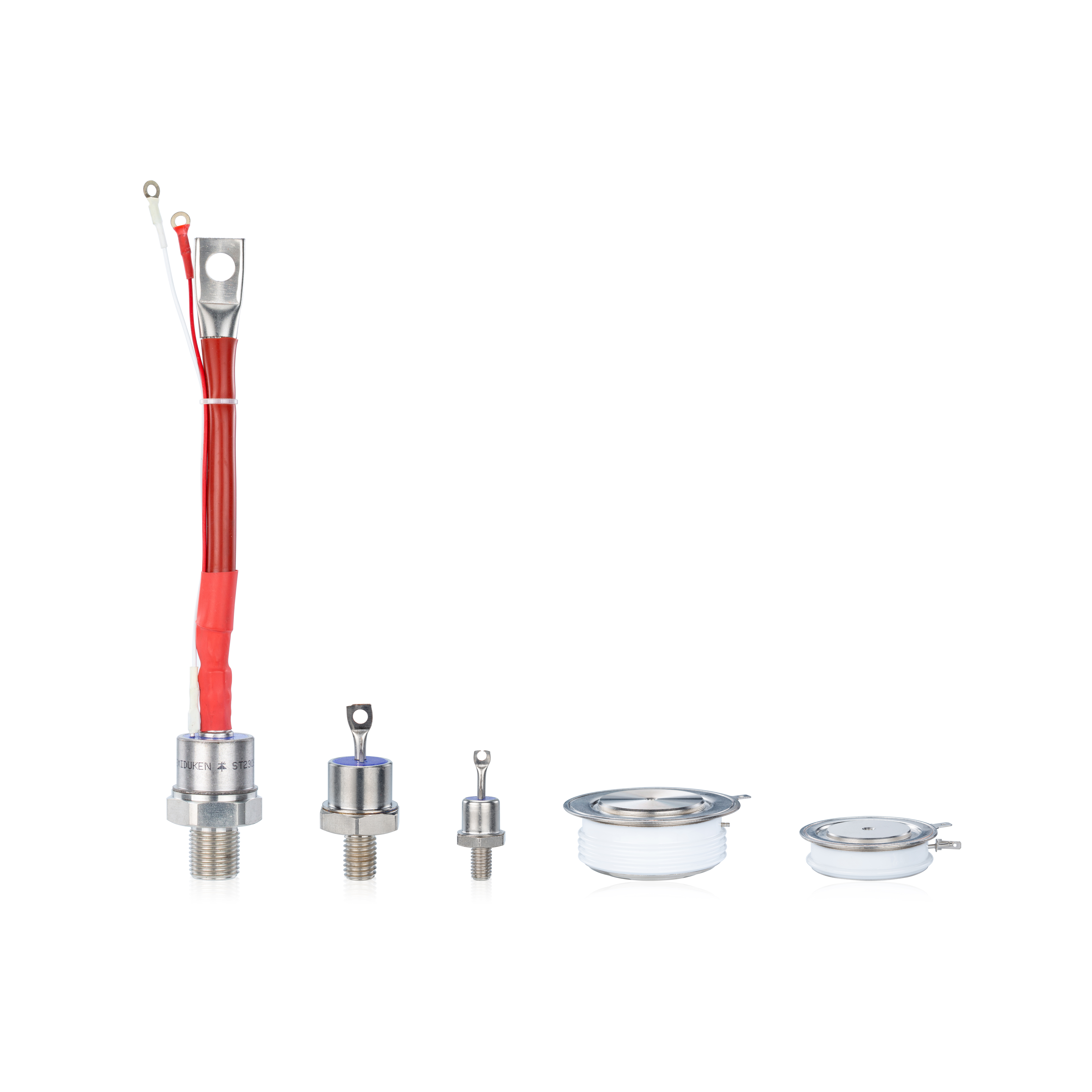
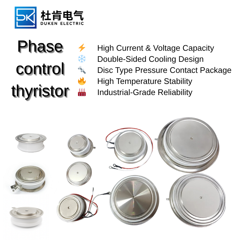
A low-loss thyristor still requires an effective thermal path. Disc devices are commonly clamped between heat sinks so that heat can leave through both pole faces. The performance of this arrangement depends on surface flatness, cleanliness, alignment, and clamping force.
An Aluminium housing disc package for electro-plating rectifiers 300A phase control thyristor can support a compact and durable power stack, but incorrect installation can cancel the advantages of the package. Uneven pressure increases contact resistance and may create hot spots. Excessive pressure can damage the device body, while insufficient pressure restricts heat transfer.
Busbar connections should also be inspected. Loose or oxidized joints produce resistive heating that may be incorrectly attributed to the thyristor. Conductive surfaces should be cleaned using approved methods, and fasteners should be tightened according to the equipment specification.
Cooling system efficiency affects the entire rectifier. Clogged air filters, weak fans, restricted water channels, or high coolant temperature increase semiconductor temperature. In many installations, restoring the cooling system produces a greater reliability improvement than simply installing a higher-rated device.
4. Match the Thyristor to the Load Profile
Different applications place different stresses on the semiconductor. Electroplating rectifiers often require stable, continuous DC current with low ripple. Drives may experience frequent acceleration and regenerative conditions. Melting furnaces can impose large load changes and repeated heating cycles.
For an Aluminium housing disc package for electro-plating rectifiers 300A phase control thyristor, continuous current performance and corrosion-resistant installation are important. The device should maintain low loss during long production runs, while the enclosure should prevent chemical contamination from reaching terminals and cooling surfaces.
For drive applications, a low on-state voltage drop for DC link rectification in drives 300A phase control thyristor can improve conversion efficiency and reduce cabinet cooling demand. The selected device must still tolerate charging current, motor acceleration peaks, and supply disturbances.
A thyristor used in a furnace should have high surge capability and robust gate triggering. The control system may operate across a wide firing-angle range as the process changes from startup to full heating. The device must respond consistently throughout this cycle.
5. Measure Efficiency After Replacement
Efficiency improvements should be verified through measurement. Before replacement, record input voltage, input current, DC output, heat-sink temperature, cooling power, and load condition. After installation, repeat the measurements under comparable operating conditions.
A replacement for melting furnace rectifiers gate trigger control 300A phase control thyristor service should be evaluated during multiple process stages. Check whether current remains balanced and whether heat-sink temperatures are consistent across phases.
An Aluminium housing disc package for electro-plating rectifiers 300A phase control thyristor should be tested during a full production cycle. Stable output current and controlled temperature rise indicate that the mechanical and thermal installation is performing correctly.
Finally, confirm that the low on-state voltage drop for DC link rectification in drives 300A phase control thyristor delivers lower losses without introducing firing or commutation problems. Measurements of device voltage drop, phase current, and heat-sink temperature can provide direct evidence.
Improving rectifier efficiency requires a system-level approach. The correct thyristor can reduce conduction loss, but gate timing, thermal contact, busbar condition, cooling performance, and load matching are equally important. When these areas are optimized together, a 300A phase control rectifier can operate with lower temperature, better stability, reduced maintenance, and improved energy performance.