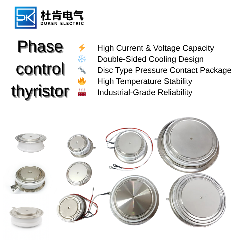
Thermal and Electrical Design Guidelines for 800A Thyristor Rectifiers
An 800A phase control thyristor can handle substantial electrical power, but its long-term performance depends on how effectively the rectifier manages heat, voltage stress, current distribution, and switching transients. Many semiconductor failures are not caused by an obviously incorrect device rating. Instead, they result from small design weaknesses that accumulate over thousands of operating cycles.
Common examples include uneven heat-sink contact, loose busbar joints, insufficient gate-drive current, excessive snubber inductance, blocked cooling channels, or underestimated ambient temperature. A successful rectifier design must therefore connect the semiconductor specification to the physical construction and real operating profile of the equipment.
1. Calculating Conduction Losses
A thyristor produces heat whenever it conducts. The conduction loss depends on the device’s on-state voltage characteristic and the current waveform. For accurate thermal analysis, engineers should use the datasheet’s threshold-voltage and slope-resistance model or the manufacturer’s published loss curves.
The current waveform in a controlled rectifier changes with firing angle and load type. A resistive load, inductive load, battery bank, and DC motor can produce different RMS and average currents even when the measured DC output appears similar. Calculations must reflect the actual conduction interval of each thyristor.
After estimating device loss, the designer calculates the temperature rise across the junction-to-case, case-to-heat-sink, and heat-sink-to-ambient thermal path. Interface materials and mounting pressure can have a major effect on case-to-sink resistance. Excessive or uneven pressure may damage the semiconductor package, while inadequate pressure increases thermal resistance.
2. Managing Insulation in High-Voltage Rectifiers
Electrical insulation and thermal conductivity often compete with each other. A thick insulating layer may improve dielectric strength but increase thermal resistance. The designer must select a material that provides sufficient voltage isolation without preventing heat from reaching the heat sink.
A battery charging rectifier robust insulation for high voltage 300A phase control thyristor assembly often uses ceramic or engineered polymer insulation between live semiconductor parts and grounded cooling structures. The final material choice depends on working voltage, transient voltage, pressure, temperature, surface contamination, and expected service life.
High-voltage battery chargers may also experience moisture condensation during shutdown or seasonal temperature changes. A battery charging rectifier robust insulation for high voltage 300A phase control thyristor design should include adequate spacing, protective coatings where appropriate, controlled ventilation, and cabinet heating if condensation is likely.
Routine maintenance must include inspection for dust accumulation, cracked insulation, loose connections, carbon tracking, and discoloration caused by overheating. Even a correctly specified battery charging rectifier robust insulation for high voltage 300A phase control thyristor can become unsafe if conductive contamination bridges insulation surfaces over time.
3. Controlling Switching Transients
The electrical network around the thyristor contains stray inductance and capacitance. During commutation, these parasitic elements can create oscillation, overshoot, and steep voltage transitions. The physical layout of the rectifier is therefore part of the protection system.
A static VAR compensator (SVC) high dv/dt immunity 300A phase control thyristor must withstand fast voltage changes while remaining off until a legitimate gate pulse arrives. Strong device immunity reduces the probability of false triggering, but external snubber components are still needed to keep stress within safe limits.
Snubber resistors and capacitors should be installed close to the thyristor terminals. Long connections add inductance and reduce effectiveness. The component values must limit dv/dt without creating excessive current or loss. A static VAR compensator (SVC) high dv/dt immunity 300A phase control thyristor application may also require series reactors, surge arresters, and synchronized control logic.
Gate-circuit layout is equally important. Gate and cathode conductors should be short, paired, and separated from high-current paths. Shielding or twisted conductors can reduce electromagnetic interference. When several devices are used in one branch, each static VAR compensator (SVC) high dv/dt immunity 300A phase control thyristor should receive a consistent gate pulse to prevent unbalanced conduction.
4. Designing for Temperature Extremes
Rectifiers operating in outdoor cabinets may be exposed to freezing conditions during startup and high internal temperatures during full-load operation. Semiconductor ratings must be checked across the complete environmental range.
A high current switching device extended temperature range (–40°C to +85 °C) 300A phase control thyristor is designed for broader environmental conditions than a standard commercial component. However, the surrounding gate driver, snubber capacitor, cooling fan, current sensor, and insulation system must support the same range.
At high ambient temperature, derating becomes essential. The allowable current may need to be reduced because the heat sink cannot maintain a sufficiently low case temperature. An 800A thyristor should never be assumed to carry its full nominal rating in an 85°C enclosure without a detailed thermal calculation. A high current switching device extended temperature range (–40°C to +85 °C) 300A phase control thyristor datasheet should be reviewed for leakage, gate, and thermal behavior at both temperature limits.
Thermal cycling can loosen bolted joints and fatigue interfaces. Spring-loaded clamping systems, Belleville washers, torque-controlled fasteners, and periodic inspection help maintain stable pressure. A reliable high current switching device extended temperature range (–40°C to +85 °C) 300A phase control thyristor installation should be validated through temperature cycling, overload testing, and long-duration operation.
Conclusion
An 800A thyristor rectifier must be designed as an integrated electrical, thermal, and mechanical system. Conduction losses determine the cooling requirement, insulation affects both safety and heat transfer, layout influences transient stress, and ambient temperature controls the available operating margin.
Engineers can improve reliability by calculating real current waveforms, using conservative voltage margins, minimizing stray inductance, controlling mounting pressure, monitoring temperature, and inspecting insulation throughout the equipment’s service life. These practices reduce unexpected shutdowns and help the rectifier maintain stable performance under demanding industrial conditions.