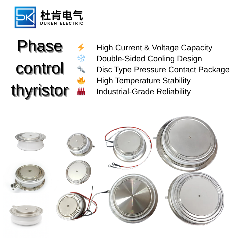
Improving Reliability and Service Life in 800A Thyristor-Based Rectifier Systems
The service life of an industrial rectifier depends on the interaction of its semiconductor devices, cooling system, transformer, busbars, control electronics, protection circuits, and operating environment. Installing an 800A phase control thyristor with a generous current rating can improve robustness, but oversizing alone does not guarantee reliability.
Long-term performance requires control of junction temperature, surge energy, gate triggering, contamination, insulation aging, mechanical pressure, and maintenance quality. Rectifier manufacturers can reduce failure rates by designing around realistic operating conditions rather than ideal laboratory assumptions.
1. Preventing Thermal Overstress
Junction temperature is one of the strongest influences on semiconductor life. Repeated operation near the maximum junction-temperature limit accelerates material degradation and increases the risk of failure during overload events. Designers should therefore create sufficient thermal margin for changing ambient temperature, blocked filters, fan aging, and load variation.
An 800A thyristor may operate at only part of its nominal current in order to achieve a lower junction temperature and longer service life. This derating is particularly valuable in equipment expected to run continuously for ten or more years.
Temperature sensors should monitor the heat sink near the semiconductor mounting area. For higher accuracy, the control system can estimate junction temperature using measured current, device-loss models, and thermal impedance. The rectifier should respond to excessive temperature by reducing output, increasing cooling, issuing an alarm, or shutting down safely.
2. Maintaining Insulation Integrity
Insulation failure can create dangerous touch voltage, damage control circuits, or cause destructive current paths through the heat sink and enclosure. Insulation must be designed for continuous operating voltage as well as temporary overvoltage and switching transients.
A battery charging rectifier robust insulation for high voltage 300A phase control thyristor requires suitable insulating interfaces, adequate creepage distance, clean assembly conditions, and materials that retain dielectric strength at elevated temperature. Small defects introduced during manufacturing can become failure points after years of thermal cycling.
Battery charging locations may expose equipment to humidity or chemical contamination. The battery charging rectifier robust insulation for high voltage 300A phase control thyristor assembly should be protected from conductive dust, condensation, electrolyte residue, and corrosive gases. Maintenance procedures should specify safe cleaning methods and periodic insulation tests.
Mechanical pressure must also remain stable. If an insulating plate cracks or shifts, thermal resistance may rise and electrical clearance may decrease. A reliable battery charging rectifier robust insulation for high voltage 300A phase control thyristor installation uses controlled mounting force, verified surface flatness, and components qualified for the expected thermal and mechanical cycle.
3. Reducing False Triggering and Transient Damage
A thyristor must remain in the blocking state until the gate driver commands conduction. Fast voltage changes, electromagnetic interference, or poor gate-cathode wiring can cause unintended turn-on. In a multi-device bridge, one false trigger may create a short circuit through the transformer secondary.
A static VAR compensator (SVC) high dv/dt immunity 300A phase control thyristor provides stronger resistance to rapid voltage changes, but system-level protection is still required. RC snubbers, surge arresters, line reactors, and carefully designed busbars reduce the electrical stress reaching the semiconductor.
Gate-driver power should be stable and isolated. Each pulse must provide adequate current across the full temperature range. A static VAR compensator (SVC) high dv/dt immunity 300A phase control thyristor may fail to turn on uniformly if the pulse is too weak, leading to localized heating within the silicon structure.
Preventive testing can identify weaknesses before field installation. Engineers should verify blocking performance, trigger consistency, commutation behavior, and snubber effectiveness under maximum supply voltage. A dependable static VAR compensator (SVC) high dv/dt immunity 300A phase control thyristor system should also be tested during network disturbances and rapid changes in reactive power demand.
4. Extending Life Across a Wide Temperature Range
Temperature extremes affect semiconductor parameters and the mechanical structures around them. Low temperature can change gate requirements and increase stress between materials with different expansion coefficients. High temperature increases leakage current and reduces the margin between operating and maximum junction temperature.
A high current switching device extended temperature range (–40°C to +85 °C) 300A phase control thyristor provides greater environmental flexibility, but every supporting component must be checked. Snubber capacitors, gate transformers, fans, sensors, connectors, insulation plates, and control boards should all be rated for the same conditions.
Cold-start testing is particularly important. The rectifier should be energized at minimum temperature and evaluated for gate reliability, control timing, fan operation, and insulation behavior. A high current switching device extended temperature range (–40°C to +85 °C) 300A phase control thyristor may perform correctly while an unsuitable auxiliary component causes the system to fail.
At high ambient temperature, the control system may need to reduce output current automatically. This approach is more reliable than allowing the device to reach its thermal limit. A long-life high current switching device extended temperature range (–40°C to +85 °C) 300A phase control thyristor design includes temperature-based derating, alarm thresholds, shutdown protection, and event logging.
5. Establishing a Preventive Maintenance Program
Even a robust rectifier needs regular inspection. Maintenance intervals should reflect operating hours, environmental contamination, load severity, and the consequences of unexpected downtime.
Technicians should check heat-sink cleanliness, fan operation, cooling-water quality, busbar discoloration, fuse condition, gate connections, clamping pressure, and insulation surfaces. Thermal imaging can reveal loose joints or uneven current distribution before they cause a shutdown.
Operational data also provides valuable warning signs. Increasing heat-sink temperature, changing firing-angle requirements, higher ripple, or repeated transient alarms may indicate deterioration. Recording these trends allows maintenance teams to replace aging components during planned outages.
Spare-part strategy is equally important. Critical facilities should maintain compatible thyristors, fuses, gate-driver modules, snubber components, and cooling parts. Replacement procedures must specify torque, clamping force, cleaning, insulation checks, and functional testing.
Conclusion
Improving the service life of an 800A thyristor rectifier requires disciplined thermal design, strong insulation, effective transient protection, dependable gate control, environmental qualification, and preventive maintenance. No single feature can guarantee reliability.
The most successful systems use conservative electrical margins, monitor temperature continuously, control contamination, test operation across the full environmental range, and record performance trends. These practices allow high-current rectifiers to operate safely and consistently in demanding industrial and utility applications while reducing unplanned downtime and lifecycle cost.