Key Technical Support Insights for Replacing 106A Thyristor Modules in UPS Systems
Introduction
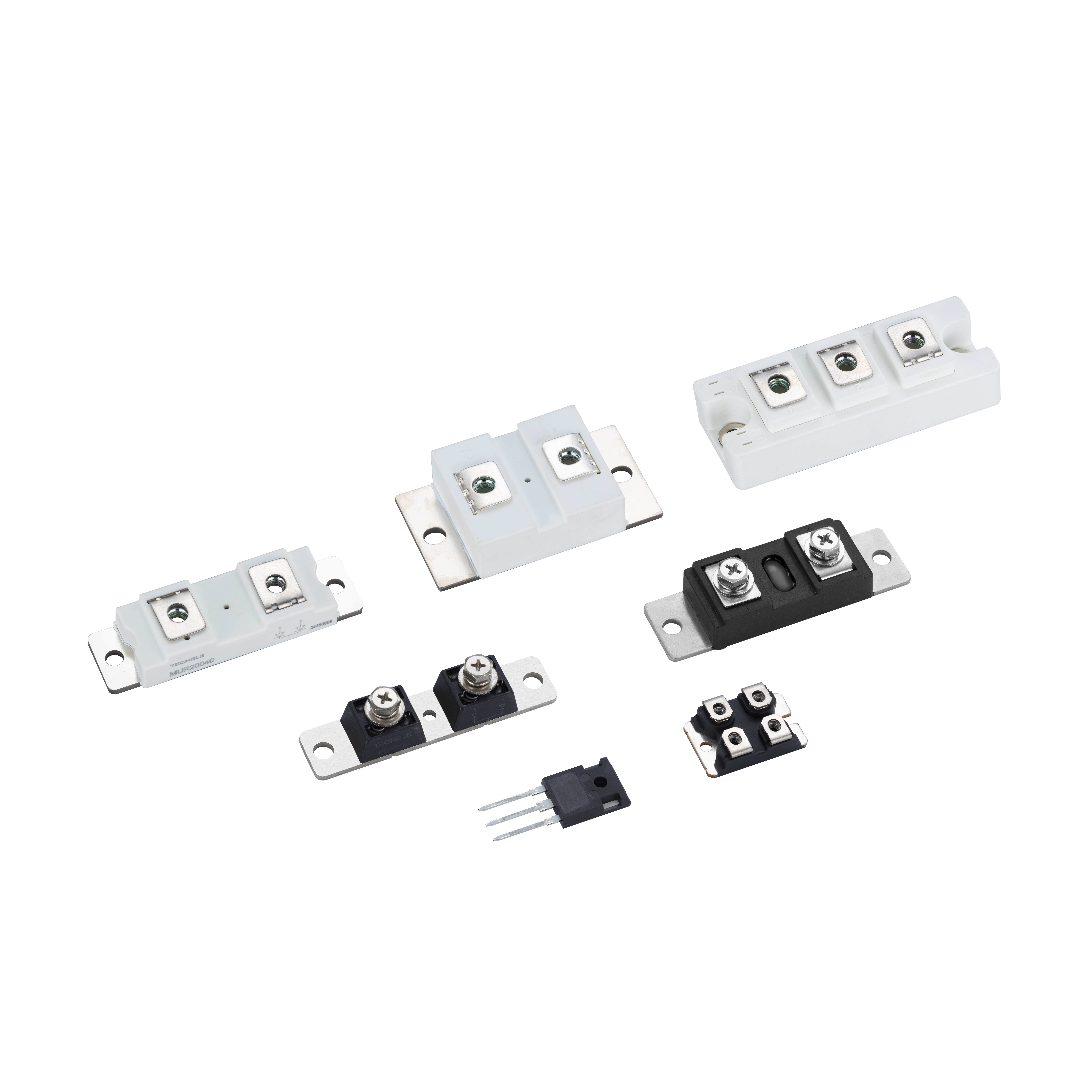
In UPS systems that underpin mission‑critical infrastructure, the performance and reliability of components such as the 106A thyristor module for UPS systems are paramount. When technical support or troubleshooting is required, engineers must understand parameters like hold‑current, low‑slope‑resistance, and correct procedures for replacement to maintain uptime. This article walks through typical fault scenarios, diagnostic methods, and best practices for support technicians tasked with module maintenance or swap‑out in industrial UPS installations.
Understanding Hold‑Current and Its Effect on Thyristor Behavior
One key specification is the module’s hold‑current — the minimum current required to keep the thyristor in conduction once triggered. If the system’s conduction current drops below this level, the device may turn off unexpectedly, leading to voltage instability or power disruption.
Troubleshooting steps include:
Measuring the load current during normal operation to ensure it exceeds the module’s specified hold‑current threshold.
Verifying control circuit gating ensures full conduction and doesn’t impose restrictions that reduce current below the hold‑current level.
Considering whether elevated junction temperature has led to increased hold‑current requirement (temperature drift may increase actual hold‑current by a few percent).
In UPS module maintenance, when you are required to execute a replacement of a 106A thyristor module, it’s important to match or improve the rated hold‑current of the original component to avoid system instability.
Evaluating Low‑Slope‑Resistance in Module Design
Another important parameter is low‑slope‑resistance, which refers to the incremental resistance seen in the conduction path as current increases. A module with low slope‑resistance produces less voltage drop, less internal heating, and reduced thermal stress.
Technical support steps include:
Use a thermal camera to monitor the baseplate of the module during steady‑state conduction. Elevated hotspot implies higher internal resistance (i.e., high slope‑resistance).
Compare the measured voltage drop across the module with the datasheet specification of slope‑resistance; a higher drop may signal early aging or damage.
When planning for replacement, ensure the new module specifies equal or better slope‑resistance to reduce heat and extend life of the surrounding heatsink or cooling system.
Step‑by‑Step Replacement Procedure for 106A Thyristor Module
When an engineer needs to perform a replacement of a 106A thyristor module in a UPS system:
Isolate the UPS and shut down input power.
Discharge all capacitors and ensure zero stored energy.
Remove the faulty module, noting the wiring of gate, cathode/anode, and any thermal sensors.
Inspect heatsink surface for flatness and cleanliness; ensure no contamination which might degrade conduction (impacting slope‑resistance).
Mount the new module, torque the screw‑terminal or bolt connections per specification. (Note: Though this article isn’t focused on the screw‑terminal model, proper connection applies to all module types.)
Apply thermal interface material and re‑establish cooling path.
Bring the system online and monitor for correct conduction current above hold‑current threshold, and stable voltage drop consistent with low‑slope‑resistance specs.
Common Faults and Troubleshooting Tips
If the module randomly turns off under partial load: Check if current falls below hold‑current.
If the module overheats under nominal load: Evaluate slope‑resistance for degradation; consider replacement.
If output waveform is distorted: Potential gate‑drive issue or junction temperature drift raising hold‑current; check module spec.
If a recent replacement fails prematurely: Ensure correct part number, matching or better specs for hold‑current and slope‑resistance, correct thermal mounting, and proper cooling.
Summary
Technical support and troubleshooting of the 106A thyristor module for UPS systems depend on a clear understanding of specifications like hold‑current and low‑slope‑resistance, and the correct execution of replacement procedures. By monitoring these parameters and following systematic replacement steps, engineers can maintain UPS reliability and avoid costly downtime.


