Evaluating Diode Configuration for 200A 400V Systems: When to Use Common Anode or Cathode
In power system design, selecting the correct diode configuration is more than a schematic decision—it affects the thermal profile, system complexity, and long-term reliability. With the growth in demand for 200A 400V fast recovery diodes, particularly in SMPS, flyback converters, and industrial heavy-duty modules, the decision between common anode and common cathode designs becomes critical.
This article evaluates both configurations, identifying key parameters and recommending usage based on application and performance needs.
1. Switching Speed and Application Demands
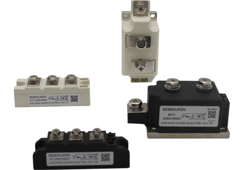
Speed matters in modern power systems. When using a fast reverse recovery heavy duty module non-isolated package 200A 400V fast recovery diode, the layout must accommodate rapid current transitions without inducing excessive EMI or heat.
Common cathode designs tend to be easier to control in non-isolated systems where gate drives share a common reference. In contrast, for differential or symmetrical topologies, common anode may offer better dynamic stability.
2. Heat Management and High-Temperature Tolerance
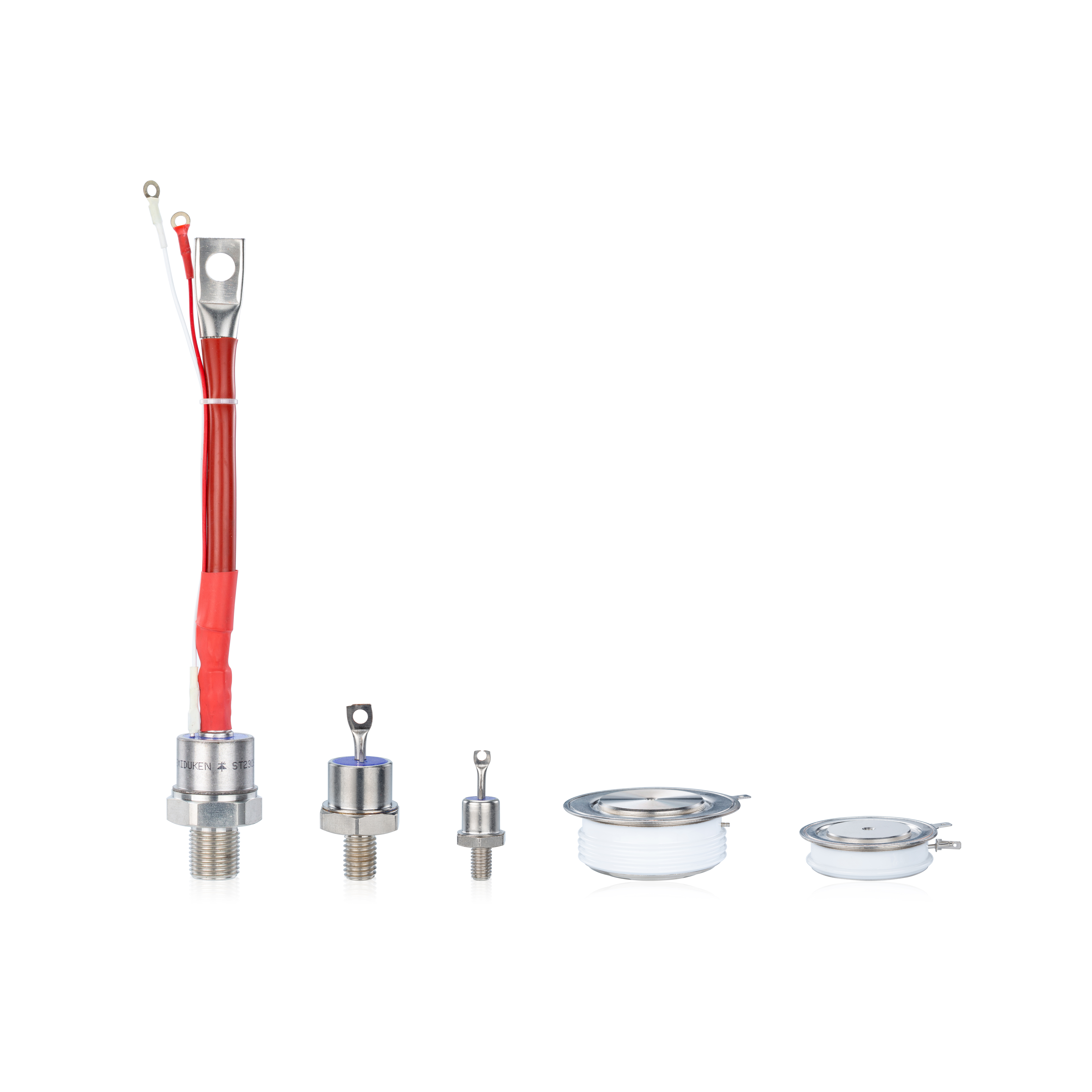
Thermal constraints define the limits of high-power components. The for SMPS high temperature 150°C soft recovery type 200A 400V fast recovery diode can operate in environments where standard diodes fail. When heat concentration is an issue, common anode configurations help by spatially separating junctions and spreading heat more evenly.
This is particularly important in power supplies operating near their thermal envelope, where driver and diode interactions can create hotspots.
3. Isolation Requirements in Transformer-Based Systems
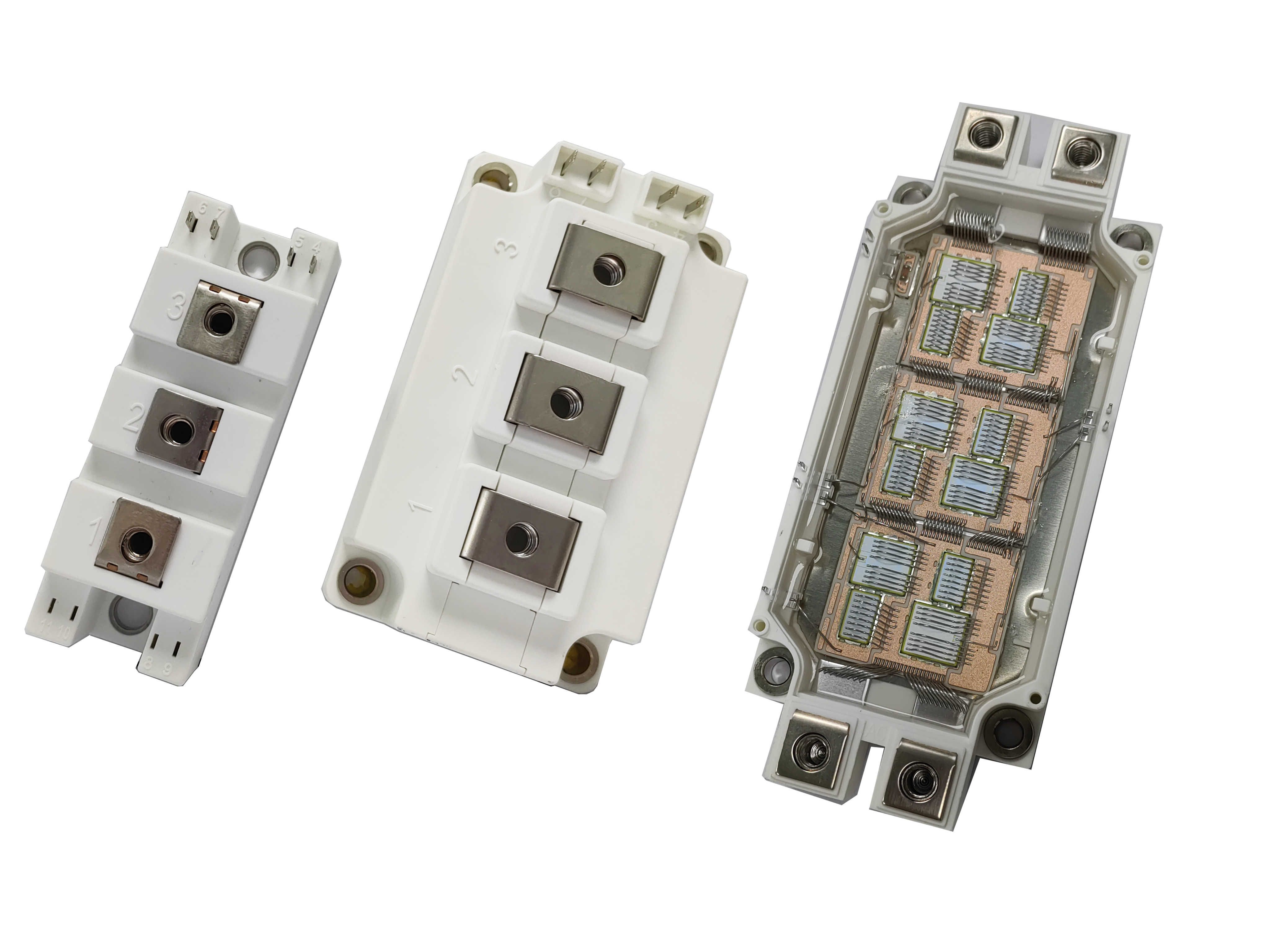
When galvanic isolation is required, as in flyback converters, packaging and polarity selection become tightly coupled. The ceramic insulated package for flyback converter for high power rectifier 200A 400V fast recovery diode supports high voltage separation and thermal insulation.
In these cases, a common anode layout minimizes PCB layer transitions and reduces loop inductance between the secondary winding and output diode terminals, improving efficiency and transient behavior.
4. Physical Layout and Heatsinking
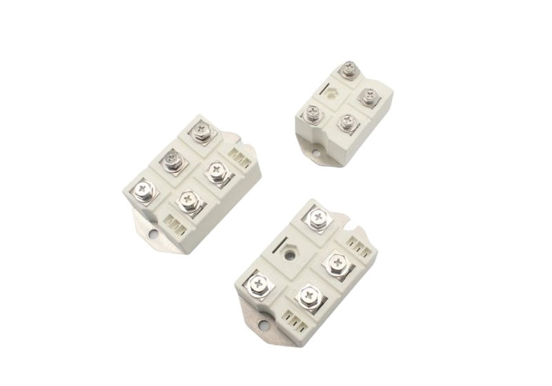
Using a fast reverse recovery heavy duty module non-isolated package 200A 400V fast recovery diode in a common cathode package allows unified heatsinking, especially when mounted in compact, low-profile industrial inverters. The simplicity of grounding and return paths can reduce board layers and cost.
However, a ceramic insulated package for flyback converter for high power rectifier 200A 400V fast recovery diode in a common anode configuration may enable distributed heatsinking across isolated regions of the PCB, enhancing modularity.
5. Final Selection Strategy
The choice between common anode and common cathode often boils down to driver architecture, packaging needs, and EMI considerations. For for SMPS high temperature 150°C soft recovery type 200A 400V fast recovery diode setups with multiple driver ICs, common anode offers control separation. For robust, high-current single-rail designs, common cathode excels in integration and simplicity.
Conclusion
Choosing the right diode configuration is as important as selecting the diode itself. Each application—whether an SMPS controller, a flyback converter, or a heavy-duty welder—presents unique electrical and thermal challenges. Modules like the fast reverse recovery heavy duty module non-isolated package 200A 400V fast recovery diode, the for SMPS high temperature 150°C soft recovery type 200A 400V fast recovery diode, and the ceramic insulated package for flyback converter for high power rectifier 200A 400V fast recovery diode provide optimized performance only when configured appropriately. Understand your system, and let the configuration amplify your design—not complicate it.