Best Practices for Thermal Simulation in 200A 400V Fast Recovery Diode Designs
Best Practices for Thermal Simulation in 200A 400V Fast Recovery Diode Designs
Efficient thermal management is essential for the performance and reliability of 200A 400V fast recovery diodes used in industrial applications such as frequency inverter drives, welding inverters, and motor drives. Without proper simulation and design, diodes may overheat, leading to efficiency loss, reduced lifespan, or failure. This article presents best practices for thermal simulation, layout design, and cooling strategies for high-power diode applications.
1. Understanding Heat Generation
Fast recovery diodes produce heat due to conduction and switching losses:
Conduction Loss: The forward voltage drop (Vf) multiplied by the average current (If_avg) during operation.
Switching Loss: Energy lost during reverse recovery transitions (Erec) adds to the thermal load.
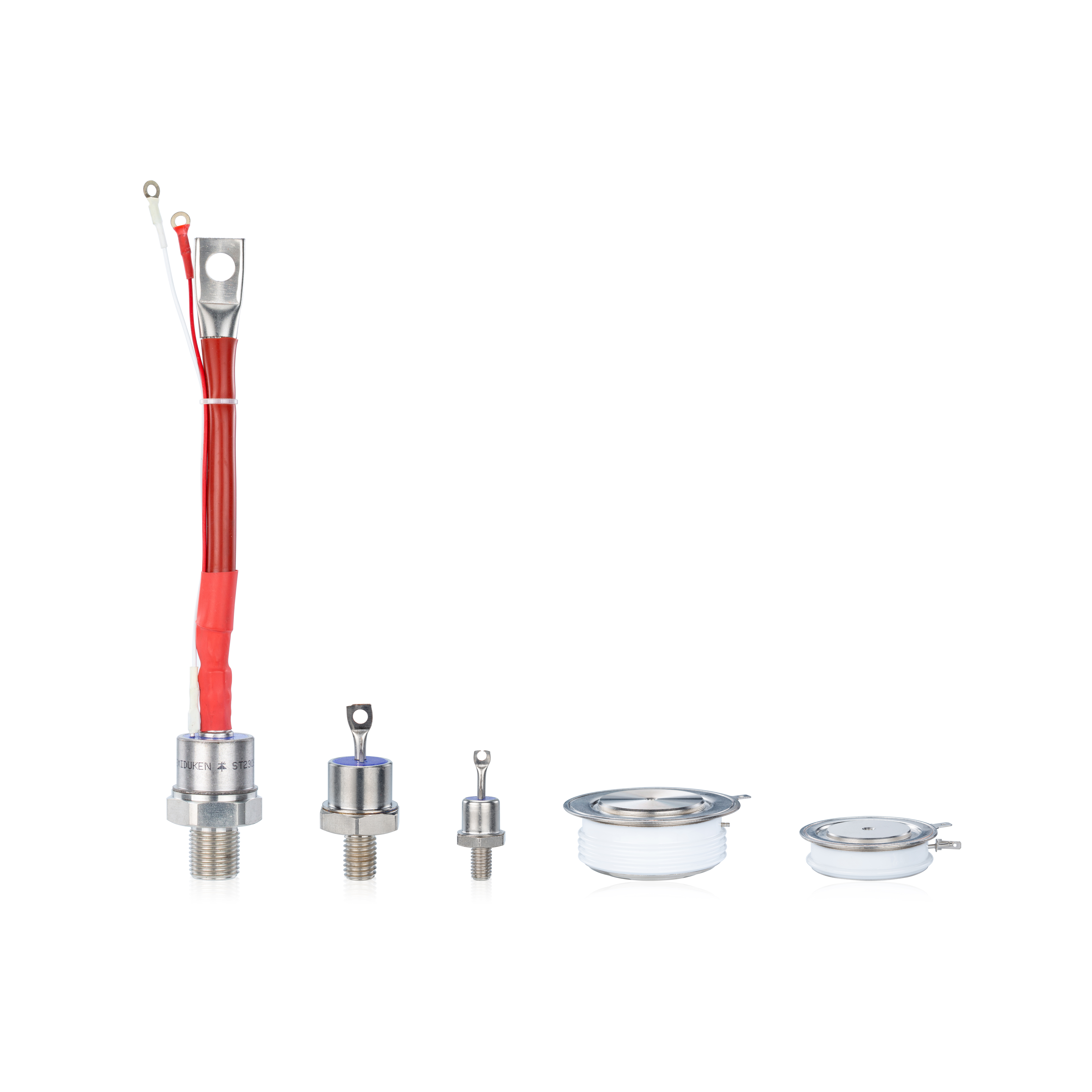
Using the sbrand Vishay equivalent for frequency inverter drives used in industrial SMPS 200A 400V fast recovery diode helps maintain predictable conduction loss, improving thermal reliability in high-frequency SMPS circuits.
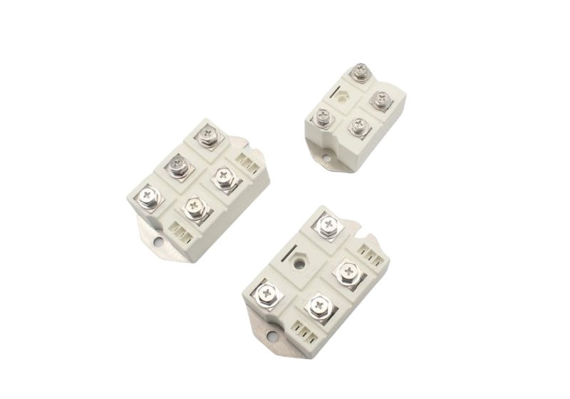
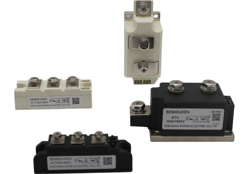
In non-isolated welding inverter designs, for bridge rectifier module for welding inverter non-isolated design 200A 400V fast recovery diode manages high peak currents with consistent thermal performance.
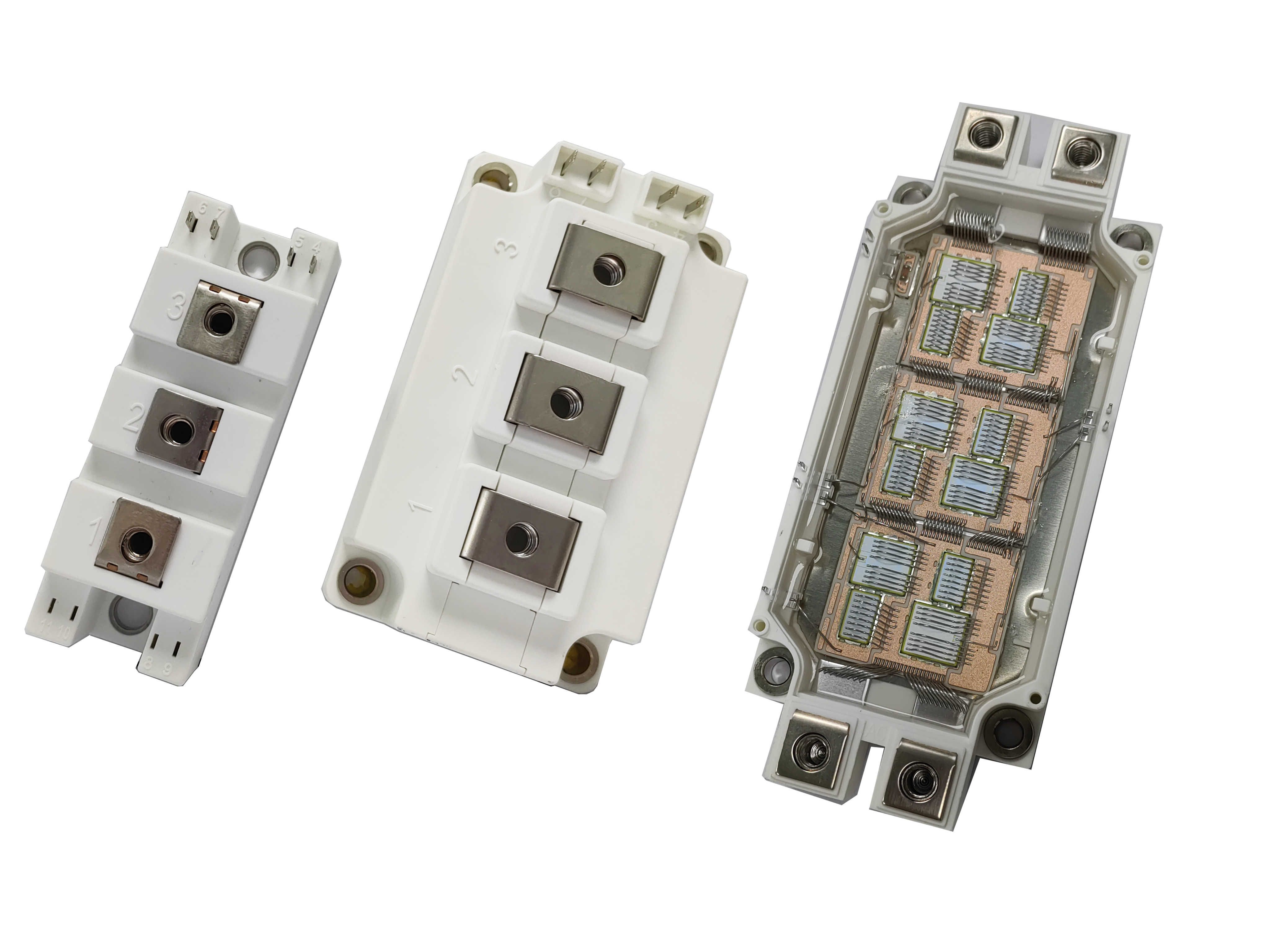
Motor drives with water cooling rely on IGBT free-wheeling diode for motor drive application water-cooled heatsink assembly 200A 400V fast recovery diode, which ensures efficient heat removal in compact inverter cabinets.
2. Creating Detailed Thermal Models
Accurate thermal simulations require modeling all thermal pathways:
Incorporate junction-to-case thermal resistance (Rth j-c) from the datasheet.
Model conduction and switching losses over operational duty cycles.
Include heatsinks, thermal interface materials, airflow, and water cooling in the simulation.
The sbrand Vishay equivalent for frequency inverter drives used in industrial SMPS 200A 400V fast recovery diode allows engineers to predict junction temperature under realistic operating conditions.
For for bridge rectifier module for welding inverter non-isolated design 200A 400V fast recovery diode, PCB-level thermal modeling ensures copper trace optimization and hotspot minimization.
Water-cooled assemblies with IGBT free-wheeling diode for motor drive application water-cooled heatsink assembly 200A 400V fast recovery diode can simulate convective cooling efficiency and temperature stabilization.
3. Simulation Tools and Techniques
Effective simulation tools include:
Finite Element Analysis (FEA) to study temperature distribution.
Transient analysis to capture pulsed and high-frequency operations.
Validation using thermocouples or infrared imaging.
Testing the sbrand Vishay equivalent for frequency inverter drives used in industrial SMPS 200A 400V fast recovery diode virtually for peak junction temperature helps define safety margins.
Simulations of for bridge rectifier module for welding inverter non-isolated design 200A 400V fast recovery diode provide guidance for optimal copper layout and reduced thermal resistance.
The IGBT free-wheeling diode for motor drive application water-cooled heatsink assembly 200A 400V fast recovery diode allows assessment of water flow, pressure drop, and cooling efficiency under full load.
4. Layout and Cooling Design
Thermal simulation informs the layout and cooling strategy:
Minimize PCB loop areas to reduce parasitic inductance and local heating.
Position diodes for effective airflow and convection.
Optimize heatsinks, fans, and water cooling channels based on thermal simulation data.
The sbrand Vishay equivalent for frequency inverter drives used in industrial SMPS 200A 400V fast recovery diode ensures proper spacing for airflow in high-density SMPS designs.
For for bridge rectifier module for welding inverter non-isolated design 200A 400V fast recovery diode, copper trace width and spacing should handle repeated high-current pulses efficiently.
Water-cooled assemblies using IGBT free-wheeling diode for motor drive application water-cooled heatsink assembly 200A 400V fast recovery diode benefit from simulation-driven cooling channel design for maximum heat removal.
5. Validation and Real-World Testing
After simulation, validate designs through testing:
Measure junction temperature under real operating conditions.
Compare experimental data with simulation predictions.
Adjust simulation parameters to reflect real-world performance.
This process ensures reliable thermal performance for sbrand Vishay equivalent for frequency inverter drives used in industrial SMPS 200A 400V fast recovery diode, for bridge rectifier module for welding inverter non-isolated design 200A 400V fast recovery diode, and IGBT free-wheeling diode for motor drive application water-cooled heatsink assembly 200A 400V fast recovery diode in all industrial applications.
6. Conclusion
Best practices in thermal simulation and management are crucial for the reliability and efficiency of 200A 400V fast recovery diodes. Accurate modeling, layout optimization, and validation testing prevent overheating and extend diode lifespan. Selecting optimized diodes for SMPS, welding inverters, and water-cooled motor drives ensures safe and stable operation.